Cooling Tower: Calculation of hydraulic pipes
When installing a water cooling tower, there is always the problem of specifying the hydraulic piping that will serve the system. Usual questions:
1. Which pump to use?
2. What is the pipe gauge?
3. What controls should be used, such as pressure, temperatures, dosage?
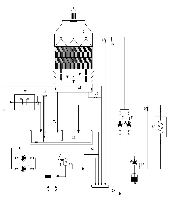
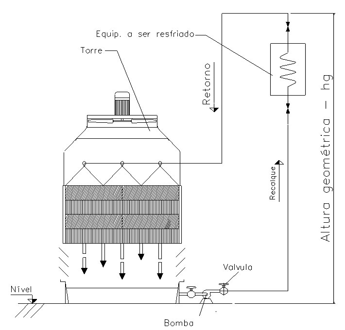
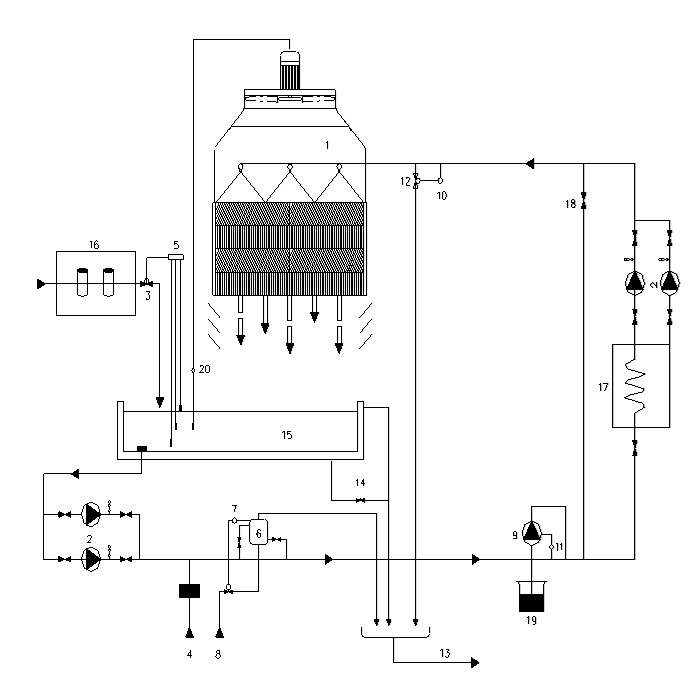
To answer the above question, it is necessary to make a decision on the hydraulic circuit diagram. For ease of understanding we present below 3 basic types.
Most used schemes
Scheme used for pipe calculation.

Tower with its own chilled water pool
Complete system

Cooling tower with 2 tanks
One tank for chilled water and another tank for hot water. This scheme is used when there are several heat sources. Each fountain pours hot water into a collection tank, from where it is pumped to the cooling tower.

Subtitle:
| 1 - Cooling tower | 11 - Ph meter |
| 2 - Pumps | 12 - Air relief |
| 3 - Fresh water supply | 13 - Sewage |
| 4 - Quick fill | 14 - Drain |
| 5 - Level Control | 15 - Swimming Pool |
| 6 - Filter | 16 – Water treatment |
| 7 - Pressure gauge | 17 - Heat source |
| 8 - Rinse | 18 – Bypass valve |
| 9 - Dosing pump | 19 – Dosing tank |
| 10 - Meter | 20 - Thermostat |
Pipe gauge - diameter
The choice of pipe diameter will determine how much capital will be invested.
The pipe diameter, for the design flow in m³/h, is a function of the water velocity inside the pipe. The ideal speed is 2.5 m³/s. In this condition, the capital invested for the construction of the hydraulic circuit and the corresponding energy consumption for pumping the water is the lowest possible. This study is for guidance, in case of doubt please contact our engineering department.
The following tables used for pipe determination:
Numerical example
| 1 - Circulating water flow - Gw | 100 m³/h |
| 2 - Tube chosen | 5 in |
| 3 - Total - estimate - of settlement and return | 20 m |
| 4 - Hg Pumping height - unevenness | 5 m |
| 5 - Pressure drop in the pipe | 0,82 m |
| 6 - We assume 5 elbows of 90° | 0,99 m |
| 7 - We assume that the pipeline has 2 valves | 0,05 m |
| 8 - We assume that the installation has a heat exchanger | 10 m |
| 9 - Tower pumping head | 3 m |
| 10 - The total head loss will be | 14,86 m |
| 11 - The pump selects (100 m³/h, against 14,86 m) | 125-080-200 of 15 hp |
Table 1: Steel pipes, smooth wall, DIN 2440

Notes: 1) Gw = water flow in (m³/); 2) v = water velocity inside the pipe in (m/s) 3) hv theoretical head loss in m = v²/2.g (gravity = 9.81 m/s²; 4) y = hv xc , loss of load every 100m, where c is characteristic for each pipe and/or fitting. The c value varies according to the tube and its gauge. For accessories, use table 2.
Table 2: Component load loss

Nomenclature used in tables 1 and 2
The pump table below is for guidance only. For a precise selection, the manufacturer of the chosen pump must be consulted. The selection of the pump is made through the desired flow, plus 20%, advisable, and the pressure drop calculated as explained above.
Example:
Flow of 15 m³/h, pressure of 25 mCA
Pump model: 050-032-200
3 hp engine
Rotor diameter: 240 mm
Head loss to be overcome in meters water column - m CA


